 Nestronics
Nestronics
Nestronics
Mixing AgNPs with capping agents can have a huge effect on the properties of AgNPs. These effects include reducing Ag+ content,
increasing AgNP quantity, changing size and stability of the NPs, affect toxicity, and affect bioavailability.
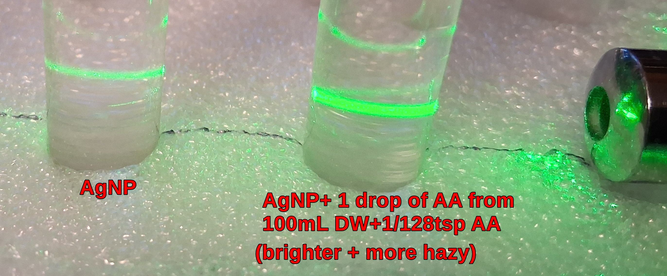
1. 1st example is Ascorbic Acid (Vitamin C).
Even very small amounts of
AA will affect AgNPs.
Shown below is an example of 1 drop of a weak AA mixture,
(1/128tsp mixed in 100mL of Distilled Water) added to a test tube of AgNPs. Notice how the green laser line
become much brighter and very hazy, indicating increased diffusion likely from increased NPs. This has likely
converted the Ag+ to AgNPs. Note that a test tube of the AA mixture has no diffusion of the green laser (not shown).
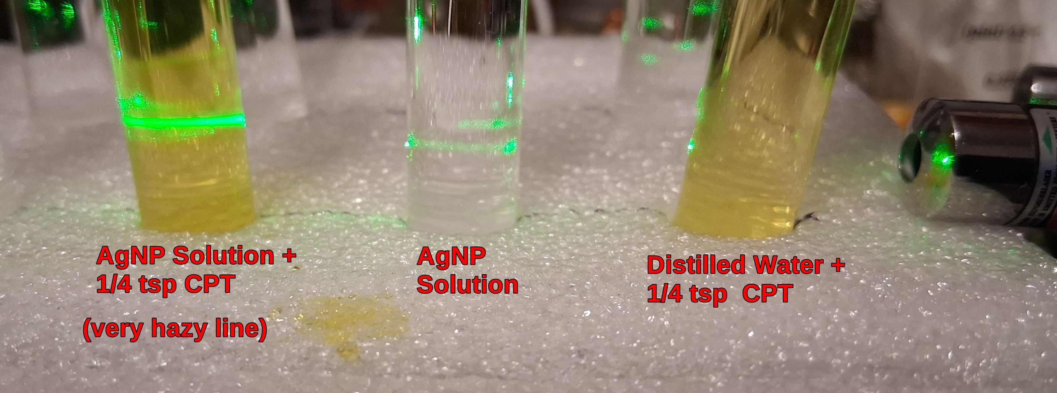
2. 2nd example is mixing in a small amount of Chocolate Peppermint Tea.
Notice how it is not the CPT that caused the line to be bright and hazy, but the mixture with the AgNPs.
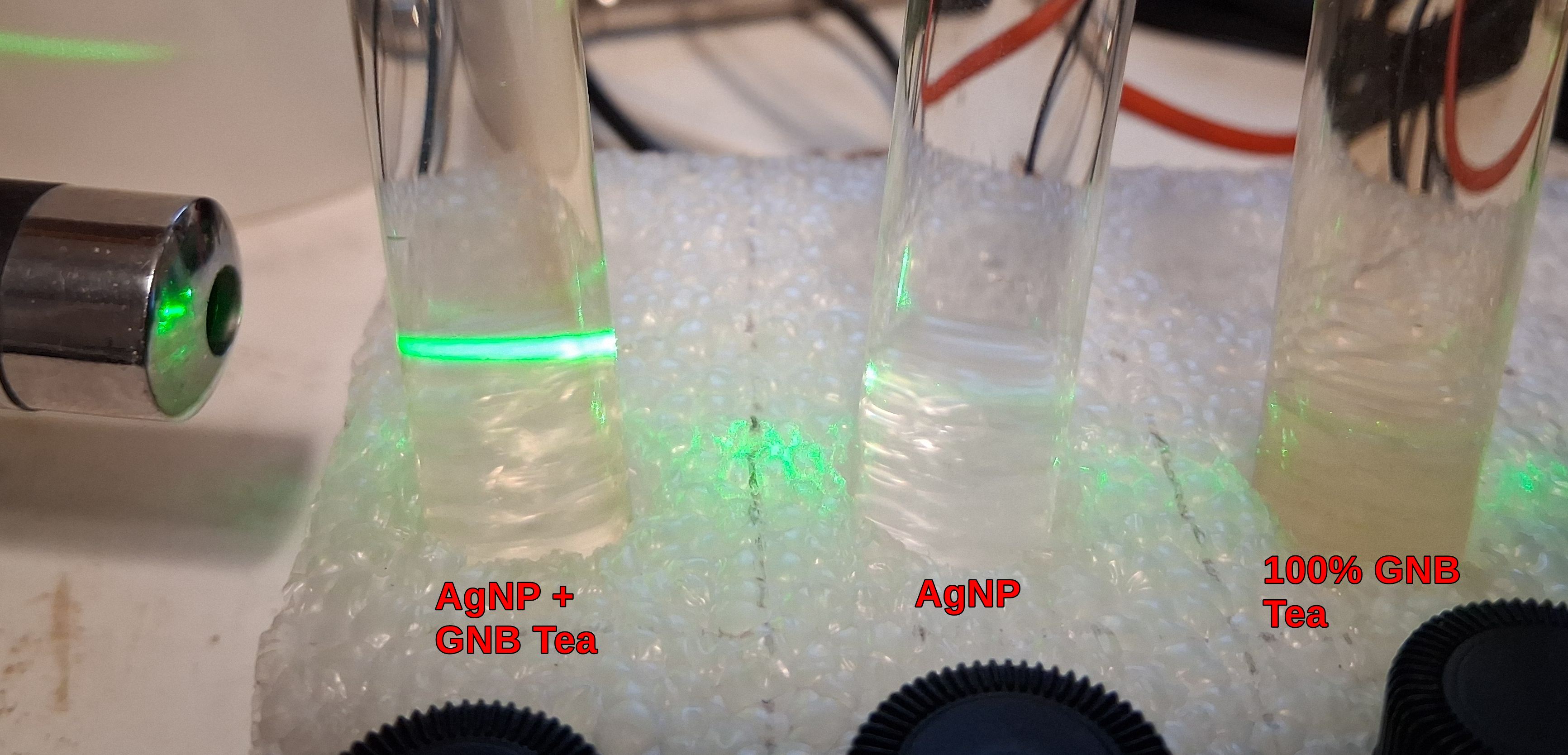
3. Next Good Night Blend Tea.
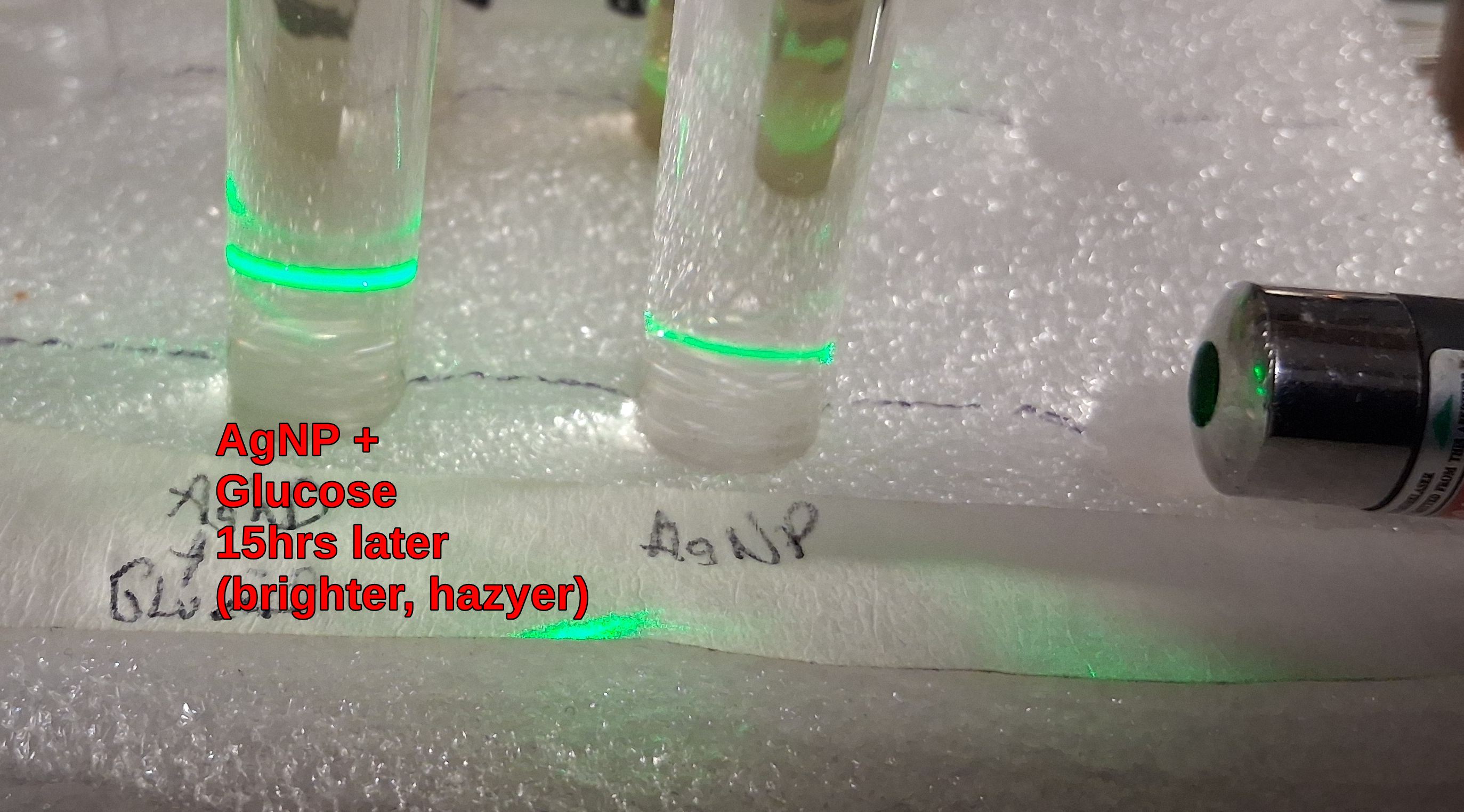
4. Glucose Capping of AgNPs.
5. Citrate,Citric Acid Capping of AgNPs is also common.
Using a TDS meter to attempt to measure the amount of AgNPs is totally inaccurate as it measures the conductivity
of the solution. This means it is more a measurement of the ionic content (Ag+) than of AgNP. AgNPs do not add
to the conductivity.
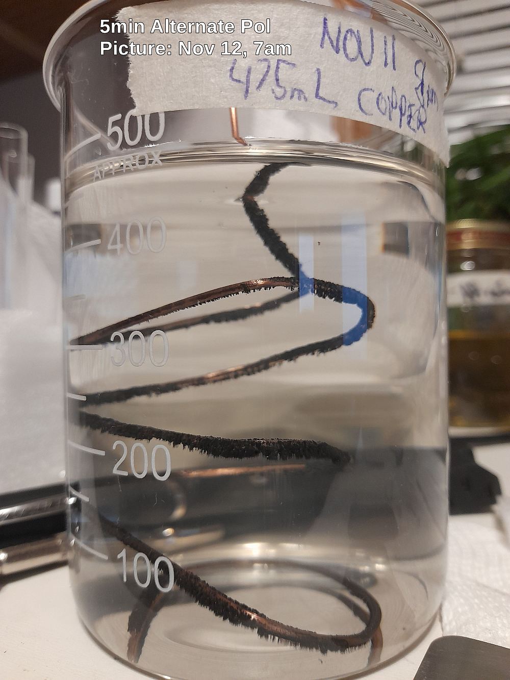
One method to estimate the amount of PPM of AgNPs in a solution is get them to plate out of the solution and weigh them.
By adding copper into the solution, silver will plate onto the copper as copper ions are exchanged into the solution.
This will convert both Ag+ and AgNPs to Silver. It is possible to tap the silver off the copper and filter the silver
with a coffee filter. The before and after weight of the coffee filter will tell you how much silver was collected.
For example if you weighed 10mg of silver from 1L of solution, you have measured 10PPM. Note you need to let the filter
air dry to the same humidity level, to help remove the weight of the water from affecting the measurement.
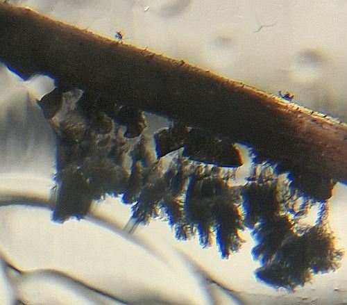
 A close up View of how the silver collects on the copper. In this case standard 14ga copper wire was used (sanded)
 We ran a calibration batch (for the AgNP generator documented below), using 4, 250mL batchs for a total of 1 Litre.
Each batch was run at 5mA, 8min Polarity Switching, and 21mins constant current (CC) run time. When done
the generator calculated a concentration of 49 PPM assuming 100% efficiency. When we plated the AgNPs out of the 1 Litre, by
inserting copper, and weighed the silver, we measured 29mg, which is 29 PPM. Hence we can estimate the actual
efficiency is closer to 60%.
We ran a calibration batch (for the AgNP generator documented below), using 4, 250mL batchs for a total of 1 Litre.
Each batch was run at 5mA, 8min Polarity Switching, and 21mins constant current (CC) run time. When done
the generator calculated a concentration of 49 PPM assuming 100% efficiency. When we plated the AgNPs out of the 1 Litre, by
inserting copper, and weighed the silver, we measured 29mg, which is 29 PPM. Hence we can estimate the actual
efficiency is closer to 60%.
Note that this plating method will not work with most capping agents like citrate.
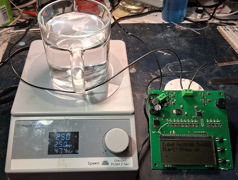
Note this AgNP generator is designed for research purposes.
It presences a possible shock hazard as the electrodes are exposed from top. Use at your own risk.
The PCB (printed circuit board) is designed to sit beside the magnetic stirrer with wires run to the electrodes
in the beaker (250ml beaker).
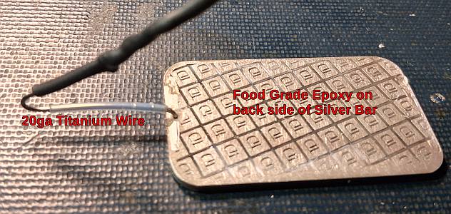
Two standard 1 oz silver bars are hooked on to the beaker edge with 20ga Titanium wire. It is powered from
a 56V power supply. I placed the beaker on a magnetic stirrer set to 250rpm.
The stirrer helps to keep the particle size smaller.
Details for the silver bar electrodes:
Note how the back side is covered in a food grade epoxy to remove it from the reaction.
This is an attempt to help keep the nano-particles small as possible.
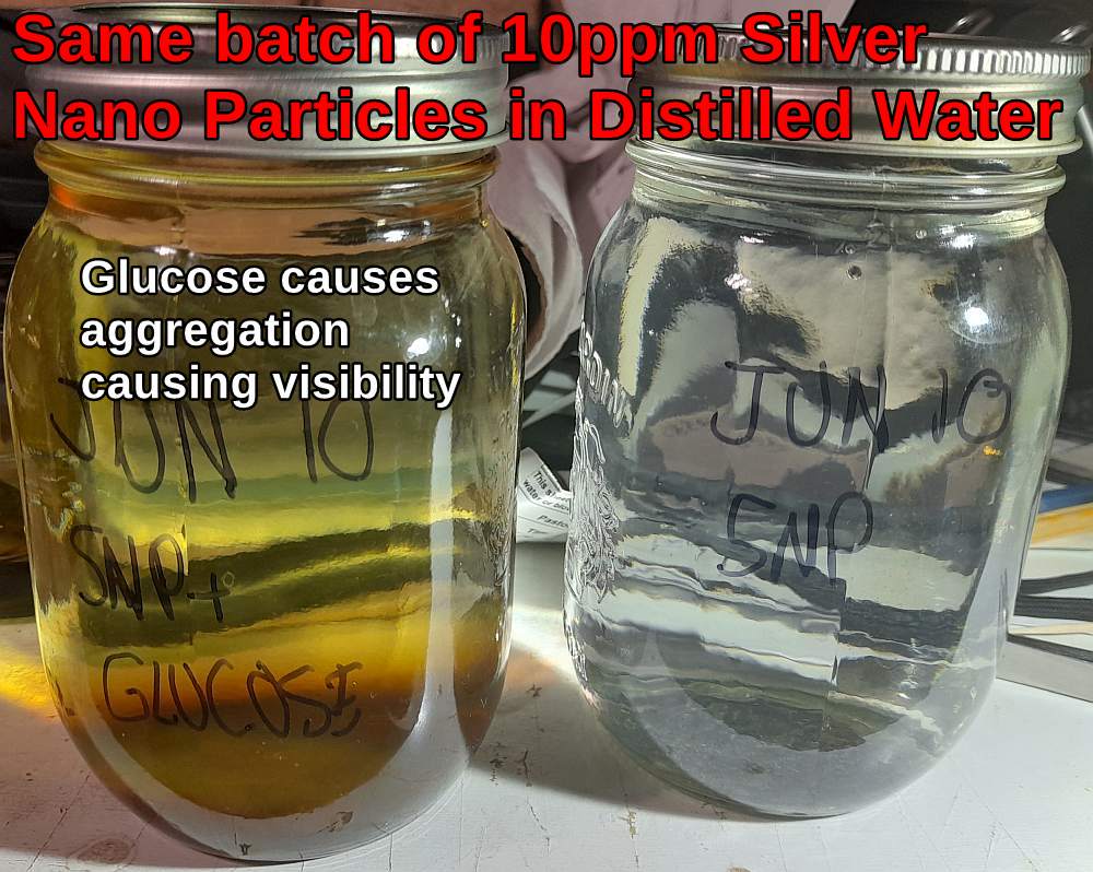
Small silver nano particles (less than 10nm) cause refraction of light in water with a laser pointer.
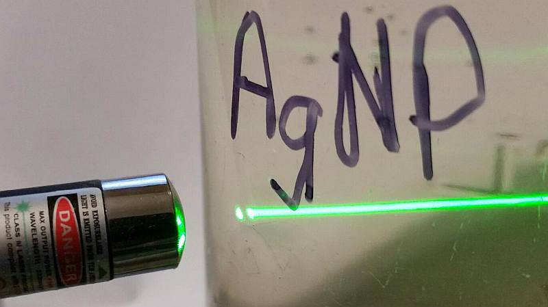
The smaller the silver nano particles the less visible they appear to the naked eye.
   Size vs Color Chart
   2nm     :   colorless
   5-10nm  :   yellow
   20-40nm :   Dark yellow to orange
   50-80nm :   Reddish-orange to Brown
   >100nm  :   Grey, blue, or cloudy

The picture below demonstates the effect. The addition of a few drops of glucose
causes the aggregation of nanoparticles causing them to become visible.
Time will also cause aggregation to larger particles, as will light exposure.
Silver Nano Particles have been used for medicinal purposes, including for cancer research.
Research from database on Silver NanoParticles and Cancer
Some of the above research includes Silver NanoParticles(SNP) combined with Magnetic Fields (MF)
The Generators are commonly available from many sources, but I have chosen to design one.
As I like to understand how they work, so I know the smallest possible nano particle size is being acheived.
Features:
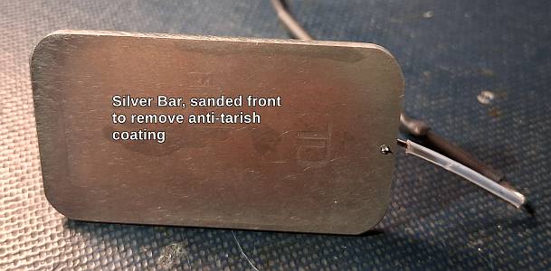
1. Uses commonly available 1oz silver bars for electrodes. Note that silver bars may have a anti-tarish coating that
must be removed.
-ensures a large electrode surface for the electrodes.
-ensures high purity for low contamination.
-long lasting
2. Targets smallest possible nano particles for increased efficacy.
- flexible current setting to optimize for smallest possible particle.
- larger current up to 1mA/cm2 can also help reduce AgNP size (must be balanced)
- plus a large spacing between the electrodes.
- mixing with magnetic stirrer at 250 rpm.
- back side of electrode epoxy coated.
3. Target for higher AgNPs (Ag0) vs ionic silver (Ag+).
- higher current helps reduce Ag+ relative to Ag0.
4. Automatic
-The MCU controlled unit, automatically monitors the current, and adjusts to keep it within 0.5mA
of the target current (for 2 sq in of electrode area)
-The unit automatically turns off when the desired AgNP PPM is reached.
- The unit computes the PPM based on theory by summing the current every second. Note the displayed value
is based on the calculated value assuming 100% efficiency. In practice it is more likely the efficiency
is closer to 60%, but this gives you the ball park area to start from. Efficiency will vary depending on
the settings used.
5. Tailored for lower ppm
- lower ppm means smaller particles, and longer lasting solution.
- the resulting water should be entirely clear.
- a laser pointer(s) (green and violet) thru the water, shows a very fine fuzzy line, indicating small particles.
6. 56V power supply.
-high voltage power supply means faster startup, as distilled water has low conductivity.
I used the PSAC30U-560L6 power supply from Digikey. If you can find a power supply that only supplies 100mA,
it would be safer. I also use a lab supply with a current limit set to 100mA.
Download the cpp code for the Silver Nano Particle Generator.
firmware download link
Download the Gerber files(in a zip file) for getting the PCB made (recommend PCBWAY).
All the information you need for ordering is in the readme.txt file.
Also remember to order the solderscreen (without frame) so you can use a razor blade (or other tool)
to squeegee the solderpaste on to the board.
Gerber file download link
Parts list and placement is in a PDF file. Most of the surface mount chip components are 0603 size so
they are fairly easy to manually place with a vacuum tool.
Parts Placement file (optimized for 2mA current) download link
The only documention missing is a schematic, which I hope to eventually draw and put up.
But you don't really need the schematic to build the unit, and it is a simple cct that can
be easily followed from the PCB. Basically the MCU controls the polarity reversal MOSFETs
(which software alternates every 8 minutes, or what ever you set it to),
then the 12 MOSFETs in the resistor ladder(0.1% tolerance) for selecting the amount of current draw.
There is a current sense resistor (20 ohm, 0.1%)
that is used by the MCU to determine when to switch the MOSFETs.
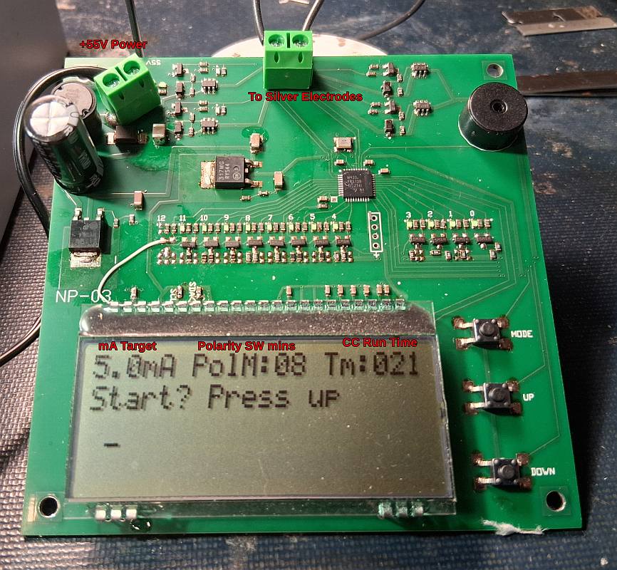
A power up sequence for the MCU verifies the LEDs are all working,
as this also helps troubleshoot the board. After the sequence the MCU displays LCD and enter into
a mode to allow changing the setting, or starting the unit. Pressing the mode button will allow
you to go thru the following settings:
-the target constant current value in mA (2mA to 10mA)
-the number of minutes before a polarity change.
-The target AgNP PPM to reach (based on 100% eff)
All selections will be saved(for the next powerup)
When done with the selections, go to the mode to allow the unit to startup, and press the up button.
It will run on the highest setting until constant current(CC) is reached. When CC is reached the 2nd timer
starts.
It is important to use good distilled water, but even that is not good enough becuase it changes with time.
You need good distilled water to avoid any undesired electrolytic reaction that will contaminate the batch.
The ADC value(indication of current draw) on the display will start at a low value when started, indicating the
distilled water is not very conductive.(only true when no pre-capping agent has been added to the water)
pH of the distilled water(DW) will affect the Ag+ vs AgNP ratio by the AgNP generator. You will want to target a ph of ~6.8–7.0. Fresh
DW will likely have a high ph like 6.8. Older stuff might be 5.5.
As the distilled water absorbs CO2 from the air the ph drops.
At room temperature, atmospheric CO₂ (~420 ppm):
Water condition	          Typical pH
Freshly DW canned	      6.8–7.0
Exposed 10–30 min	      6.2–6.5
Exposed 1–2 hours	      5.7–6.0
Exposed overnight	      5.3–5.6
This ph difference will have a hugh effect the the AgNP outcome, if not controlled or corrected.
You can adjust the pH of the water before use in the AgNP generator.
One option is Trisodium Citrate Dihydrate, which will also act as a capping agent:
Example Starter Solution: 500mL Distilled Water(DW), add 120mg Trisodium Citrate, mix, then add 10-30mg citric acid to adjust the
ph back down to 6.6-6.9 range.
Amount of Citic Acid may vary from batch to batch depending on the DW.
Then add 10mL of this "starter solution" to the 250mL of distilled water (that has been boiled and sealed in mason jar to cool, ie pH close to 7).
Cover the beaker with plastic wrap to reduce CO2 from affecting the pH, and run the AgNP batch, with 8mA target current, 8min polarity
switching, and 30PPM AgNP target.
This acheives:
- makes the solution more conductive for faster startup time to reach CC (constant current)
- very low Ag+ levels (as confirmed by TDS reading of only 13 PPM after batch is done)
- bright and hazy laser lines confirming small the AgNPs.
- on an example setting of 4mA(CC), and 31min run time, a calculated AgNP of 34 PPM (assumes 100% eff) is reached.
Solution is almost clear, with only a slight yellow tinge.
As the batch is run the ph will rise for example to 8.7. You may optional adjust this down (improves storage stability)
by add some weak solution(0.002M) of citric acid until the ph is maybe 6.8-7.
pH ≈ 6.5–7.2 is generally considered the sweet spot for AgNP bioavailability.
Here is a demonstration of the effect of an ordinary LED lamp light affecting the AgNP quality.
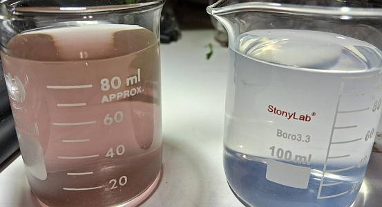
This the same batch of AgNP solution divided into 2 beakers. The right beaker was covered with a cardboard box.
After only 40 mins exposure, the difference in color (and hence degradation) is very noticable.
If your objective is low Ag+ content, you can improve the quality by using a wide mouth 150mL-250mL flask with a silicon rubber stopper.
The wide mouth is required to fit the silver bar. Inner neck diameter ~32mm for #7 stopper.
You can optionally wrap the silicon rubber stopper in plastic wrap to further reduce O2 and CO2 and block contamination.
The advantages are:
- better controlled exposure to the air, reducing O2 and CO2 from getting into the Boiled/Cooled Distilled Water.
- closer electrodes improves conductivity of the distilled water. This means less starter batch (citrate + citric acid) is required
- shorter batch run time
- small advantage possibility in smaller AgNPs, and less Ag+.
- still uses sanded silver 1oz bars with back side coated in food grade epoxy.
- still used titanium wires with teflon sleeve for hanging bars.
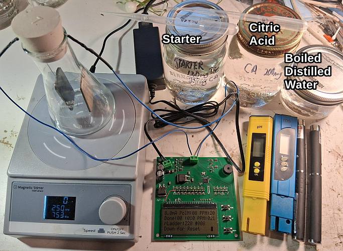
Tools are also shown in the picture: Green and violet laser pointers, TDS and pH meters.
Example Batch:
Setup 8mA, 8min Polarity Switching, 20PPM target
-use 200mL of boiled/cooled distilled water in the flask with 3mL of the Starter batch solution.
-turn on magnetic stirrer at 250 RPM
-batch runs 10 minutes all in constant current mode.
-when batch is done pH is >9 and corrected down to 7.2 with 6mL of the Citric Acid (CA) Solution.
-final TDS measures 12ppm.
-green lazer line becomes visible within 1 min of start, and very bright, finely hazy when done.
-finished color is basically clear, with perhaps very light milkly appearance
-color will start to darken to yellow/brown after 24 hours(if exposed to light), as AgNP particles become larger.
-recommend storage in amber bottles with polycone cap, with little air headroom.
Note:
Starter Batch is: 500mL Distilled Water + 120mg Citrate Acid + 25mg Citric Acid (pH 6.5)
CA Solution is: 500mL Distilled Water + 200mg Citric Acid power
AI analysis yields:
"Citrate-to-silver ratio (mass basis)
• 0.9 mg citrate : 4.0 mg Ag
• Ratio ≈ 0.22 : 1
For electrochemical AgNPs:
• ≥0.15 : 1 → stable
• ≥0.20 : 1 → robust
• ≥0.30 : 1 → conservative / over-capped
You are now solidly in the robust zone.
Your addition of ~6 mL CA solution to bring pH to ~7.2:
• Is chemically correct
• Does not strip citrate from AgNPs
• Reduces further Ag⁺ release
• Improves storage and biological compatibility
A final TDS ≈ 13–14 ppm under these conditions implies:
• Majority of silver is nanoparticulate
• Only a small fraction is ionic"