 Nestronics
Nestronics
Nestronics
This example is a very simple design to drive up to 3 coils at a typical 10 Hz rate. This method does not use resonance
so the energy used for each pulse is not reused for the next pulse. It is best to run from a 12V/5A supply to help handle the peak
surge current requirements.
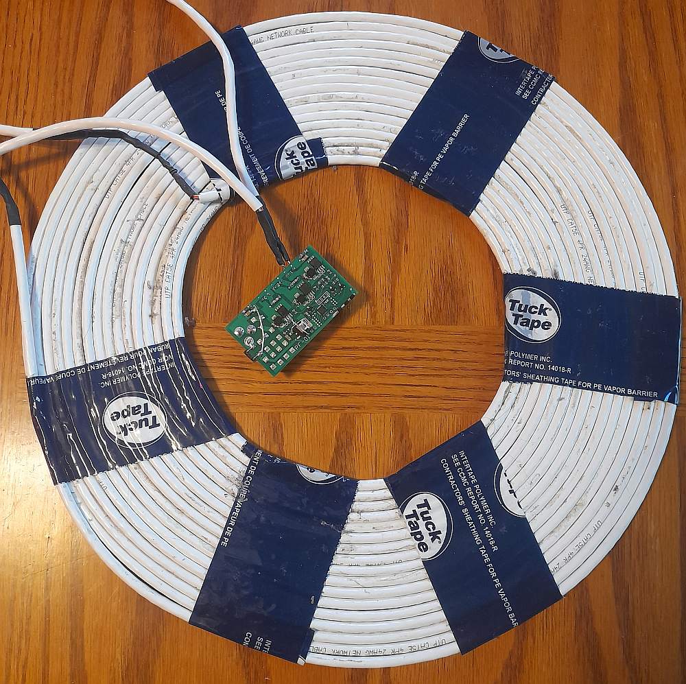
The coil is constructed from CAT5e standed cable. All 4 pair of wire are connected in parellal. This helps to lower the resistance
of the coil and the standed wires ensure flexibility, and helps to ensure low AC resistance for the rising pulse
(skin effect).
The Inner diameter of the hole is 18cm with 16 turns of CAT5e, yeilding about a 37cm outer diameter. The direction of the magnetic field is
horzonital over the CAT5e, and switched to vertical in the center area.
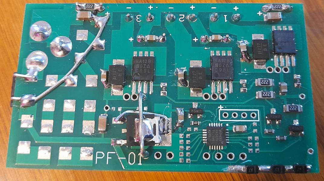
The revision one board (PF-01) is shown below, but it has been updated to PF-02 to remove all the "rework" performed to the board.
Firmware for the MCU
The MicroController is a Texas Instruments MSP430FR2433.
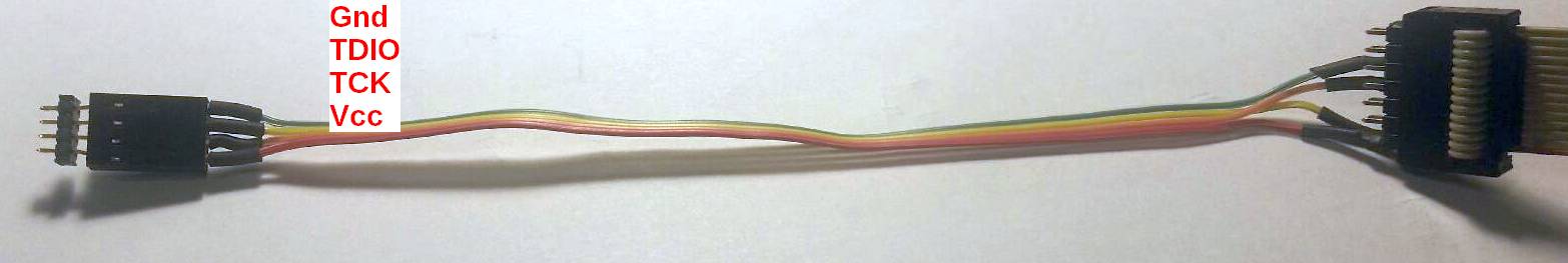
It can be programmed using the CCS (Code Composer Studio) that is free from TI.
or a Flash Emulation Tool.
In both case you need to build a custom 2 wire (4 wires with power and ground) programming cable.
firmware download link
Gerber files for the Printed Circuit Board (PCB)
The PCB gerber files: download link
They can be ordered from any PCB manfacture. We would recommend PCBWAY.
Ensure to order the solderscreen that is also in the zip file.
The part placement is available in the following PDF file:
download link
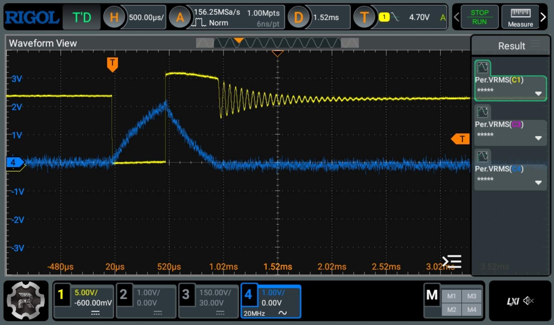
Details of Timing
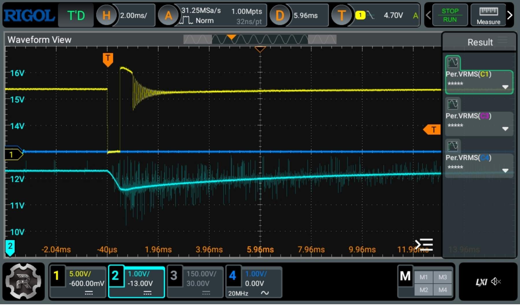
The code has been programmed to generate a 500us pulse. The blue trace is the measured magnetic field which shows a peak of about 2mT measured 5cm
above the coil (to allow for compressed memory foam mattress topper).
The field strenght decreases as the distance increased, but with a large coil like this the effect is reduced.
Note that 2mTp (1.4mT RMS) over a time period of 500us yields a rate of change of 2.8T/s.
The guideline for ICNIRP workplace exposure is 2.7T/s.
Below is shown the power supply voltage when the pulse occures. Notice it caused the power supply to go into current limiting
and the on board electrolytic caps (4700uF * 4) have a discharge and recharge curve.
In this example the caps take 10ms to recharge which limits the maximum pulse repeation rate.
The 1A fuse is a slow blow type to ensure it does not blow during the pulses.