 Nestronics
Nestronics
Nestronics
Index
Controller Details
Schematic
C++ Firmware
Gerber Files
Coils
Details of Timing
Prototype test results
Changing the Frequency of Operation
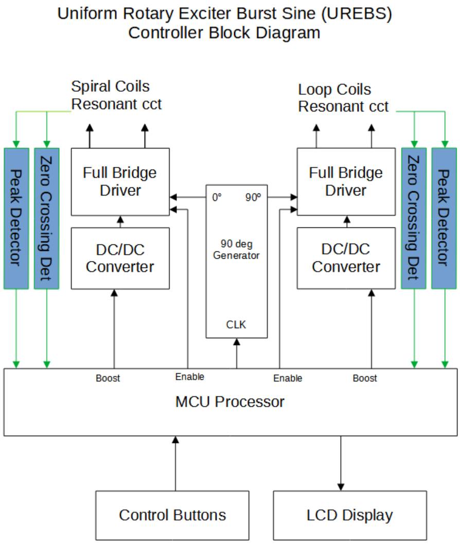
The MCU generates a clock signal at twice the desired resonant frequency, and outputs it to a hardware circuit that divids it by two, and generates 90 deg phase difference.
The enable lines are used to control the burst ON and OFF times. Individual DC/DC converters drive each full bridge circuit to allow individual adjustment of each magnetic field.
The boost line allows the DC/DC convert voltage to be boosted during the start of the resonant burst, to allow a faster rise time on the burst.
Individual Zero crossing detectors, and peak detectors allow feedback to the MCU of the peak resonant voltage and phase of each coil pair.
Since the exact phase at resonant can vary in accuracy, the MCU is capable of adjusting the phase relationship (in a feedback loop) to ensure the resulting produced phase difference is 90 degs.
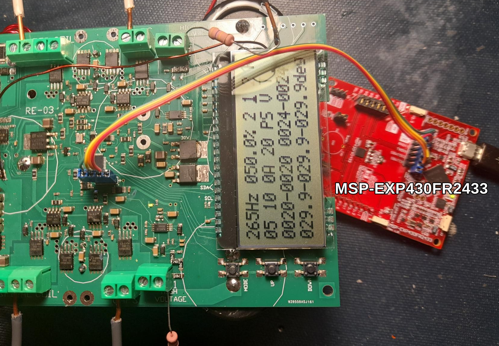
Shown below is revision 3 of the PCB which has parallel DC/DC converters to allow a high drive level.
(Note that Revision 4 uses 55V supply)


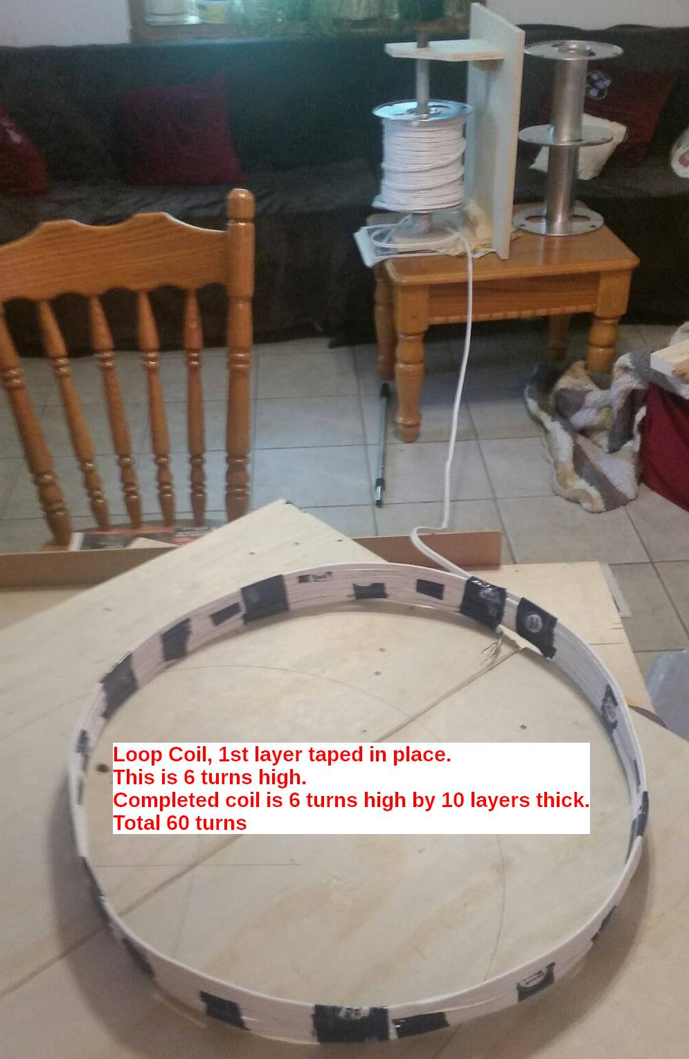
Toroid Coil Construction: 12 1/2 turns of 20ga magnet wire(6 wires in parallel) on a 19.5x33.5x11.1mm yellow/white core
Each wire should be 24" long. The 6 parallel wires yields a series resistance of 3.3mOhms.
Also since the switching frequency is about 200KHz the 20ga wire keeps the skin effect low, keeping the resistance low.

A Capacitor bank is used for each of the two resonate circuits. The resonate frequency is manually tuned for 265Hz (or desired freq) by increasing/decreasing
capacitance for the peak resonance voltage. The 2nd resonance(the one lagging 90 degrees) is also tuned to ensure and approximate 90 phase shift.
The MCU will autotune the phase once the initial manually tuning is down. Ideally 90 degrees matches a duty cycle of 50%. The MCU changes the duty cycle
to fine tune the phase.
The Capacitors should be rated for pulse use and have a high RMS voltage rating. Here the capacitors are the Kemet R75 series with a RMS voltage rating of 600V.
Great caution should be used when working with the high voltage produce by this circuit. Use all caution to prevent electrical shock/death.
Note the Schematic has different pages selected by the tabs.
Link to the SchemeIt schematic and bill of material for the UREBS01
Detailed Component Selection
Firmware for the MCU
The MicroController is a Texas Instruments MSP430FR5739IRHAT that has 16KB of FRAM.
It can be programmed using the CCS (Code Composer Studio) that is free from TI.
You can program it with an Experimenters board
or a Flash Emulation Tool.
In both case you need to build a custom 2 wire (4 wires with power and ground) programming cable.
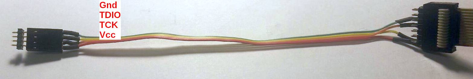
firmware download link
Gerber files for the Printed Circuit Board (PCB)
UREBS revision 4 gerber files
can be downloaded from PCBWAY.
Note please review the readme file for instruction on order parameters.
You would also want to order a solder screen, to allow assembly of the board.
All our PCB's are build by hand, using air tool placement, and reflowed in a low cost portable reflow oven.
Thru hole components are then installed.
A part placement guide can be downloaded here .
We commonly print out a few copies and use different colors of highlighters to mark same value of components.
This greatly speeds the placement rate.
You will also note that the below described hall effect sensor is also on the same layout.
If you want to build a hall effect sensor we recommend you cut it out with scroll saw before building it.
If you don't need the sensor, just do not populate that area.
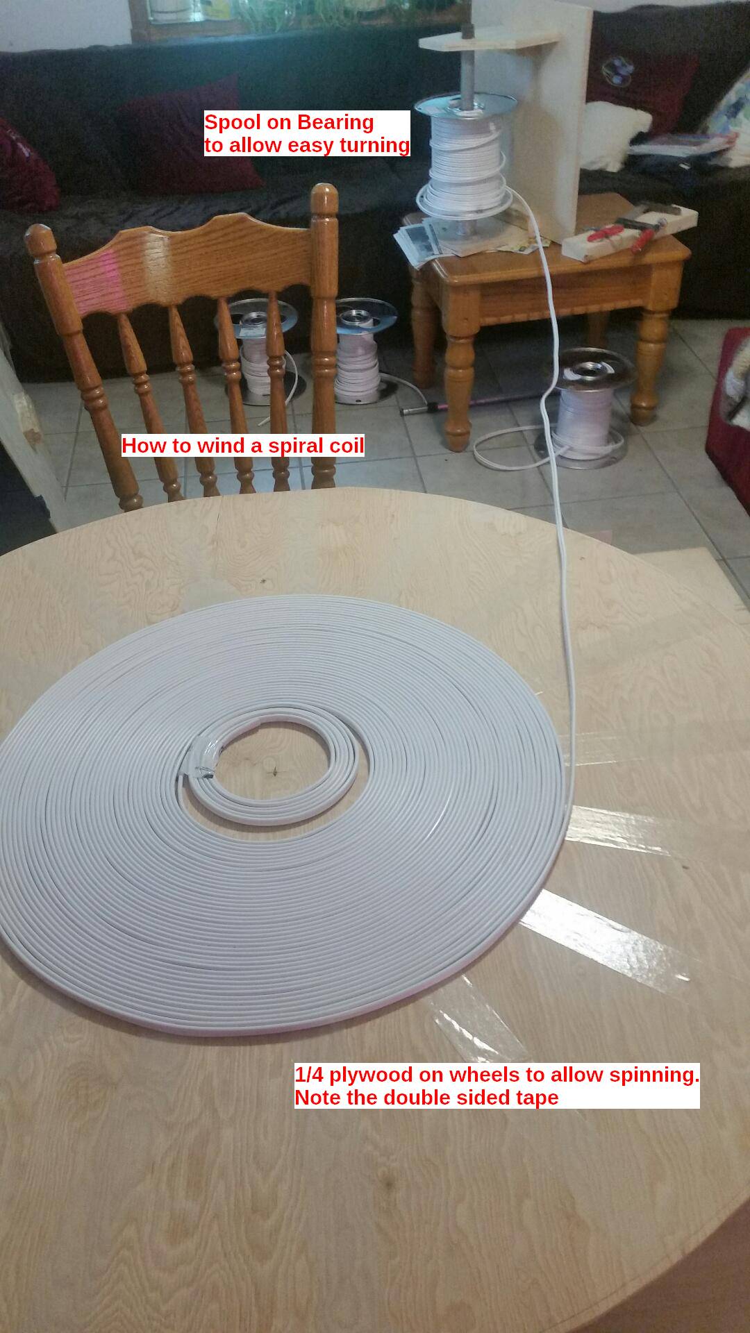
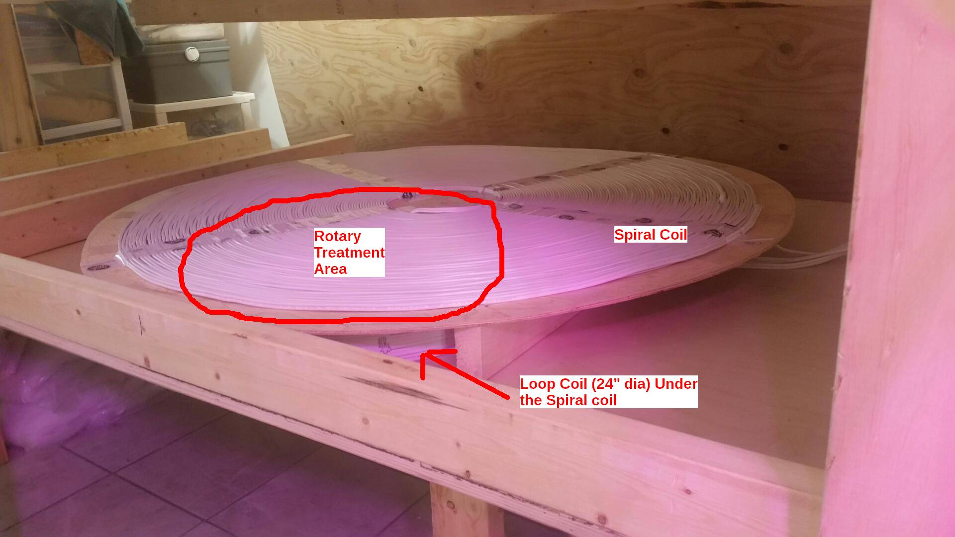
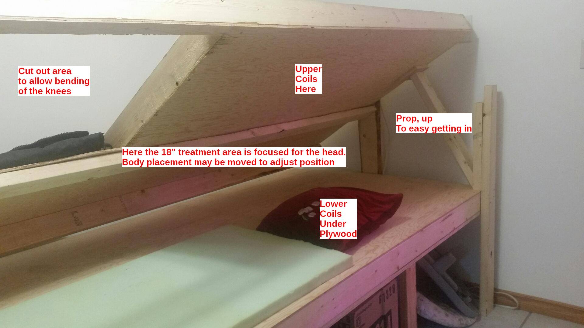
Prototype Bed (Coil Construction) Pictures
This research version has the coils installed in a bed. This potentially would allow for treatment while sleeping.
A timer could be used to control the treatment time.
Details of Timing
The phase relationship is measured by the PCB and automatically tuned to maintain a 90 degree relationship.
This a requirement to create the rotating field.
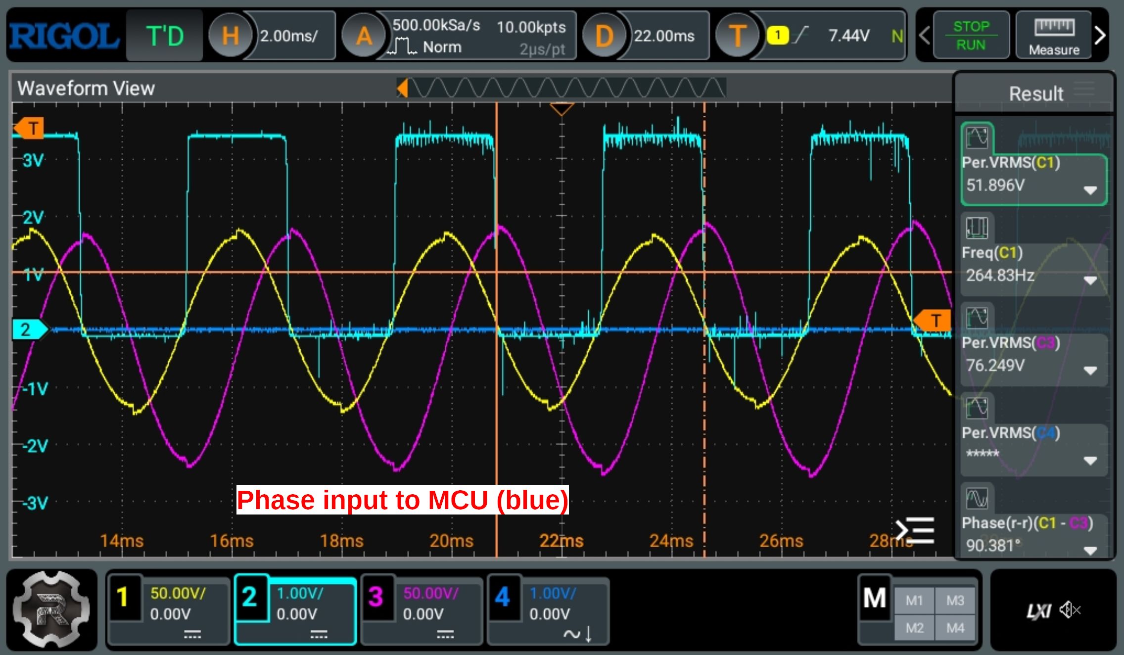
The phase is measured from the feedback high voltage signal. It is voltage divided down, and feed to the MCU.
The below image shows in blue the signal for the MCU, generated from the yellow high voltage resonance.
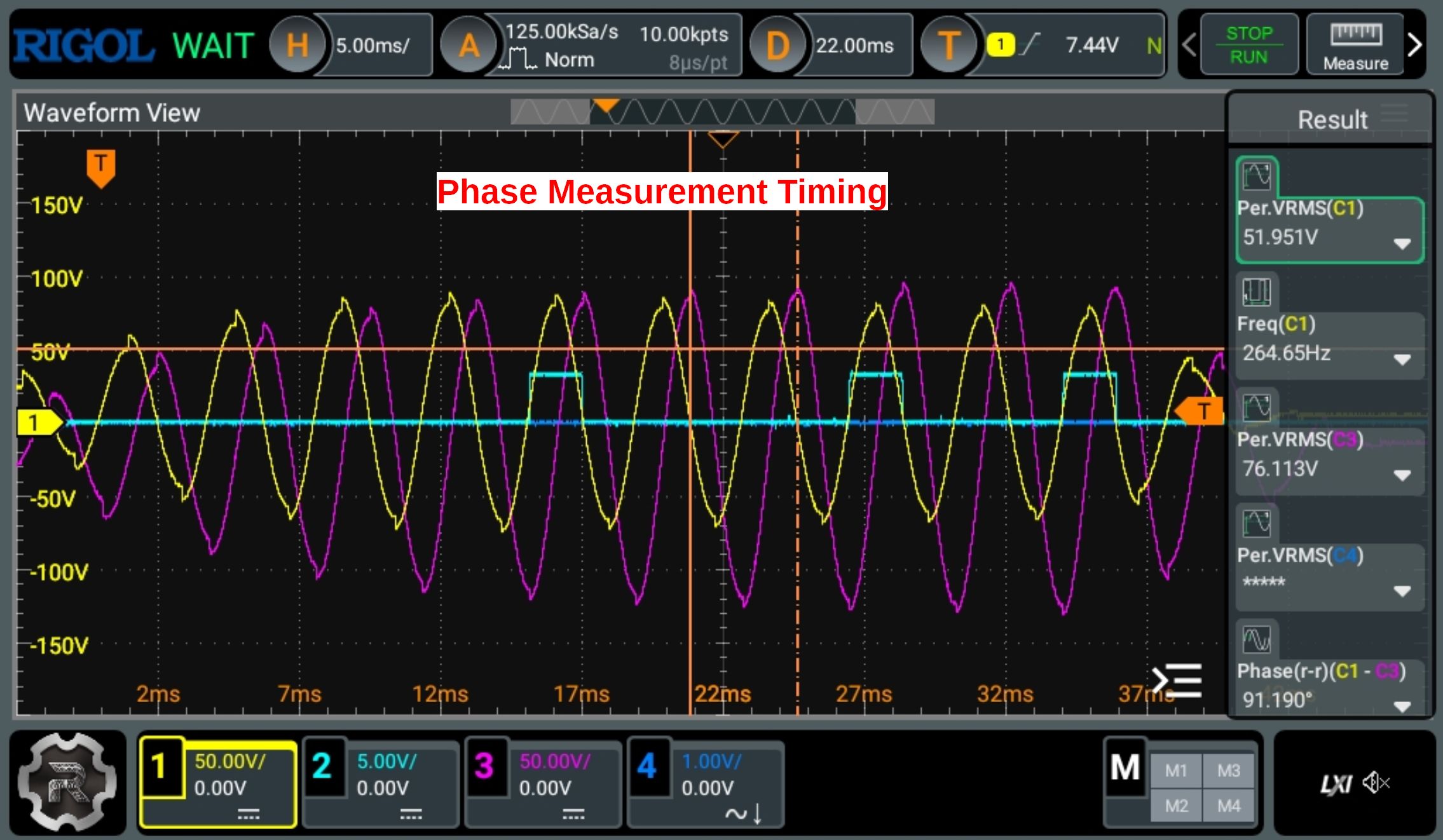
The phase will vary slightly through out the burst interval, so the firmware measures the phase at 3 different points in the burst.
(shown below in the blue trace)
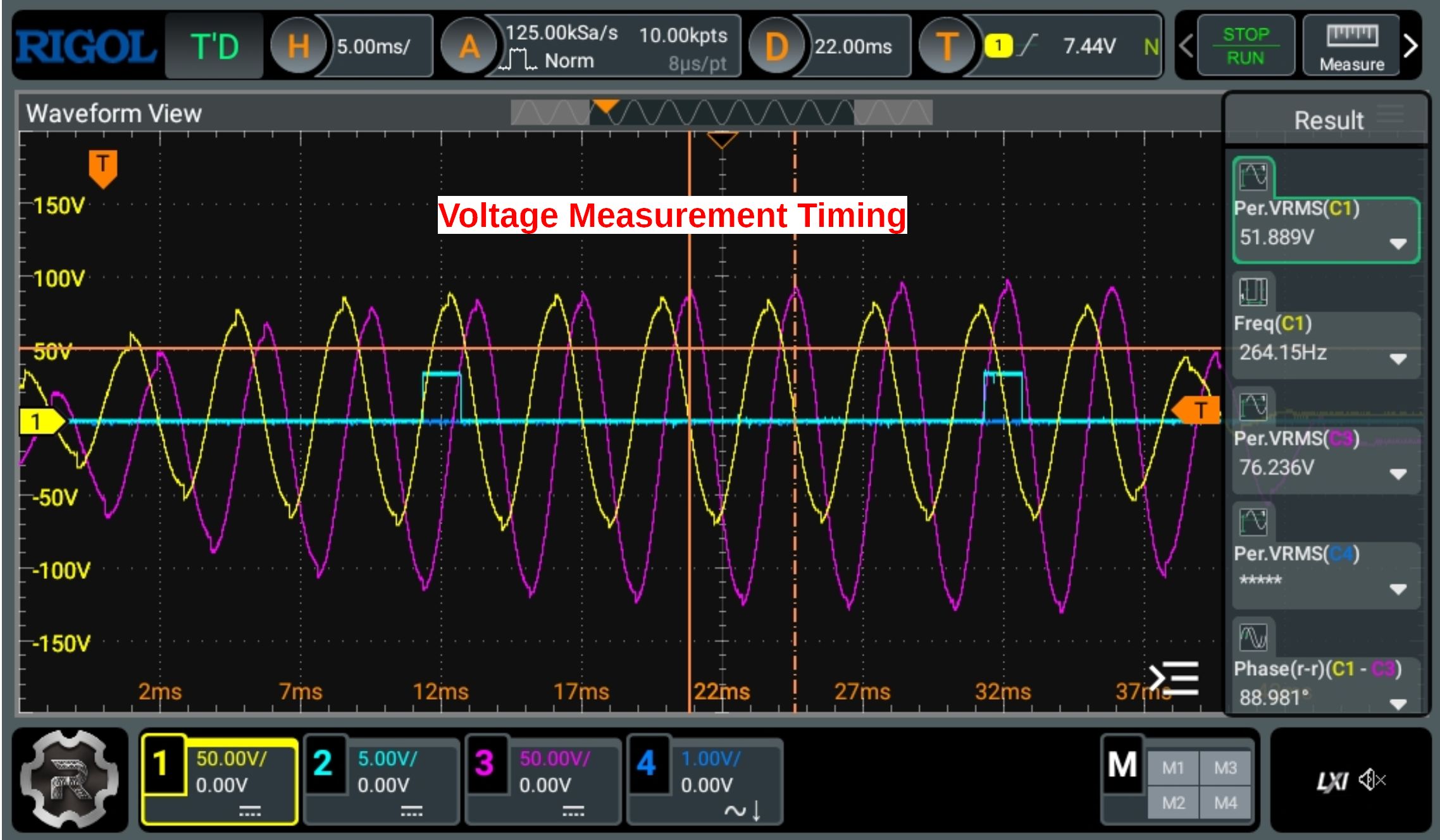
The voltage of the resonance is measured twice during the burst (shown below with the blue trace)
These voltages are measures 128 times and averaged from the output of an analog peak detector. The peak detector responce is shown below.
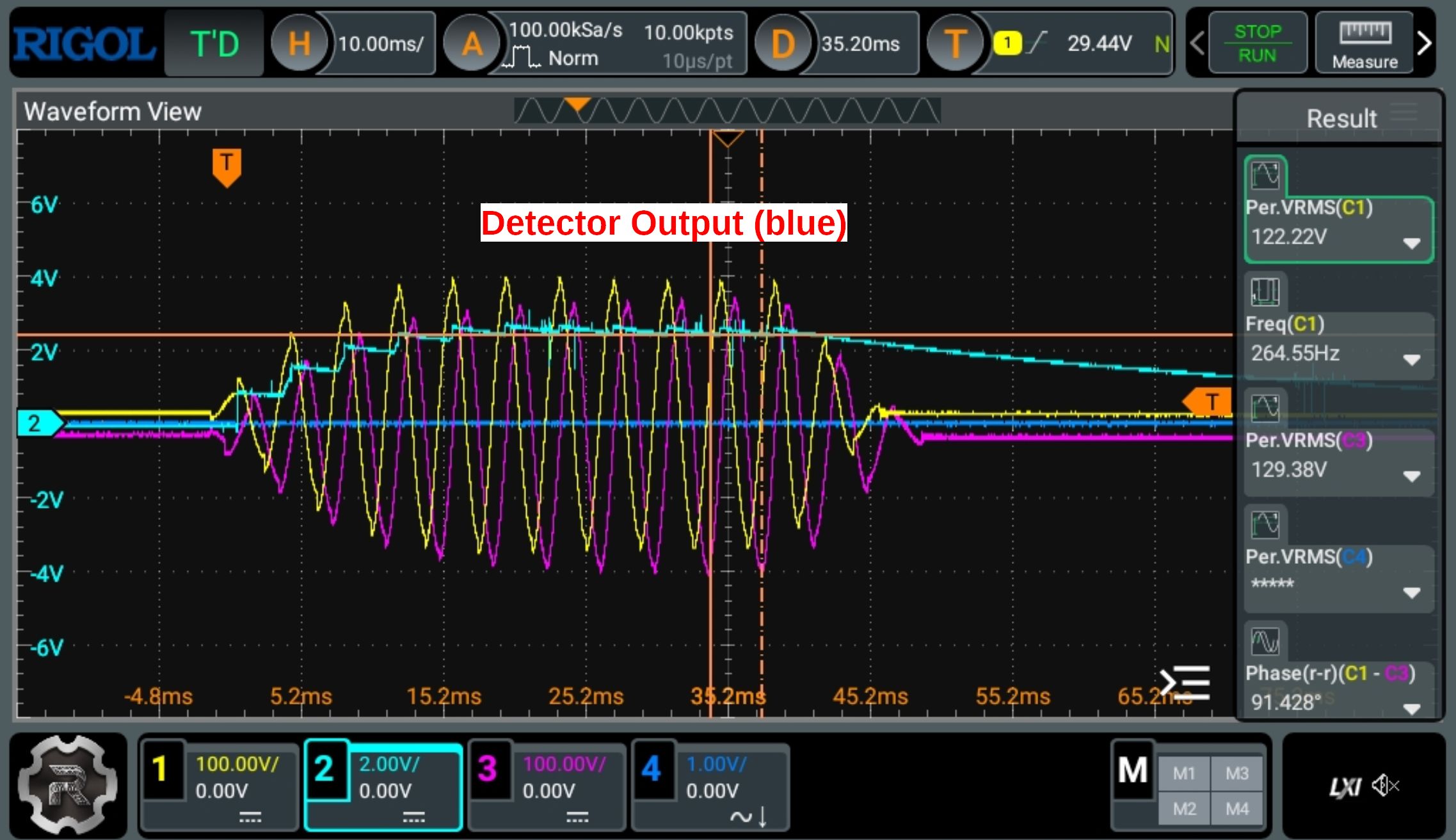
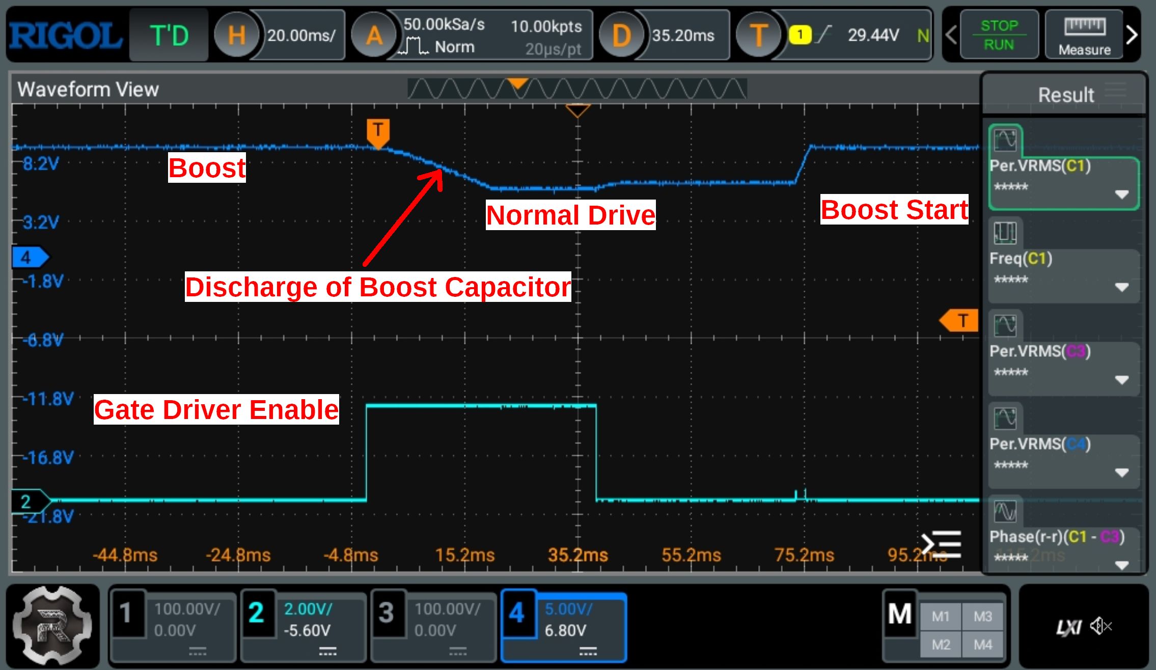
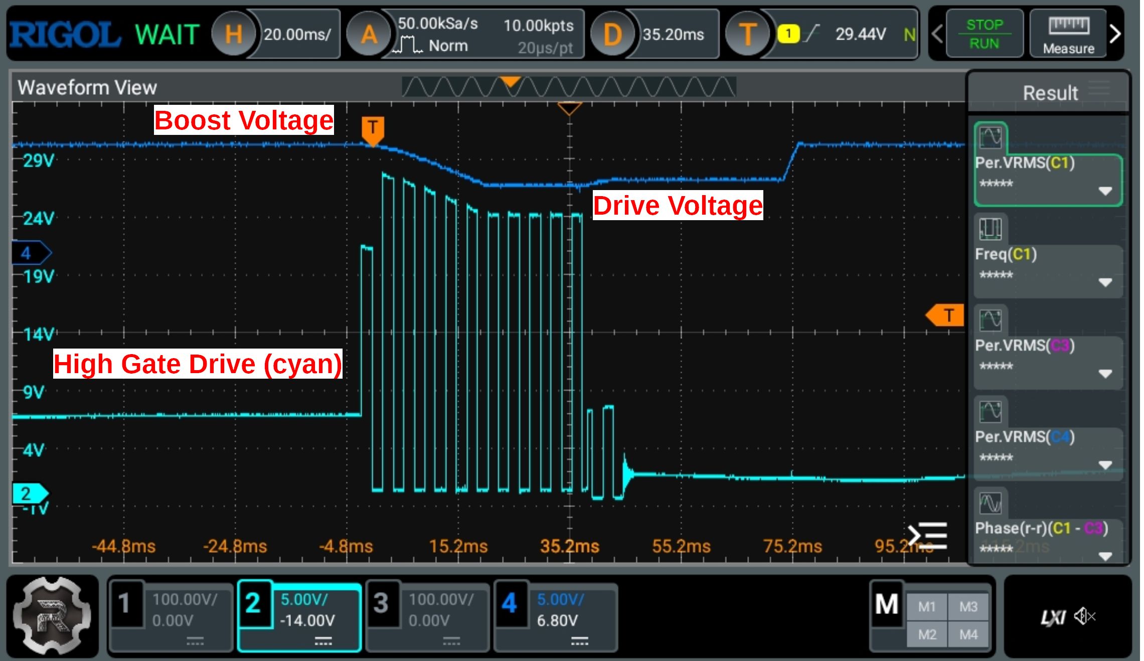
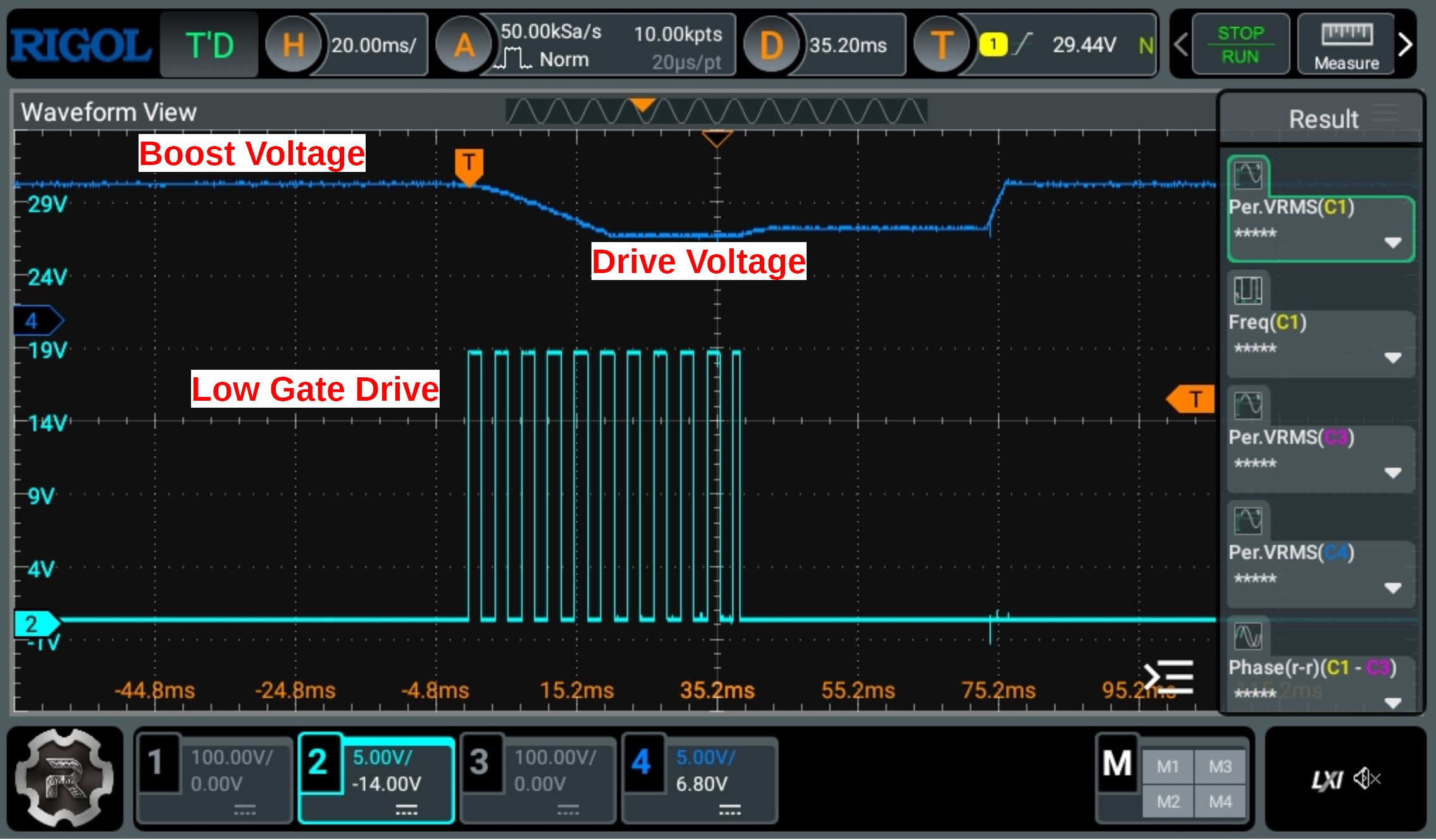
Next there is the voltage boost used at the beginning of the burst timing to decrease the burst rise time.
Test Results: Field Strenght
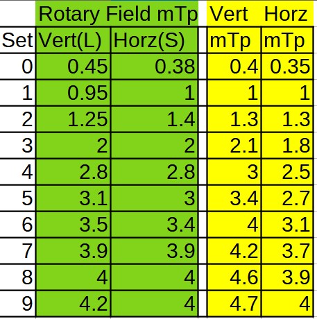
Revision 3 of the UREBS is capable of Rotary, Vertical, or Horizontal Magnetic Fields, adjustable in 10 steps from 0.4mTpeak to 4mTpeak.
Burst time is 40ms, and the repetion rate of the burst is adjustble from 4 per second(4 Hz), to 1 per 2 seconds (0.5Hz)
However settings above about 3mT may exceed the specifications of the MOSFETs and reduce their lifespan.
As an design for research purposes this is acceptable.
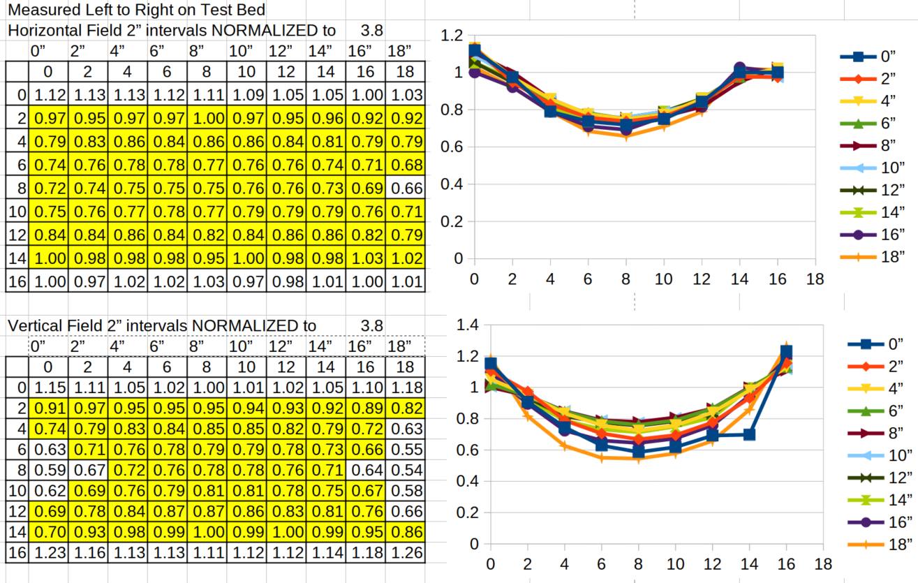
Test Results: Field Uniformity
The uniformity of the magnetic field vs distance is perhaps the most important measurement.
As shown below there is a noticable concave effect to the magnetic field.
This is because the distance used exceeds the distances used in a helmholtz configuration, as we don't need a perfect uniformity. Our goal of 0.5 was deemed acceptable.
Assuming allowance for some practical limitation such as use of a thin 2" mattress for comfort, and upper clearance, the goal is acheive.
If you reduce the treatment area from 18" horizontally to 14" a uniformity ratio of 0.7 is acheived.
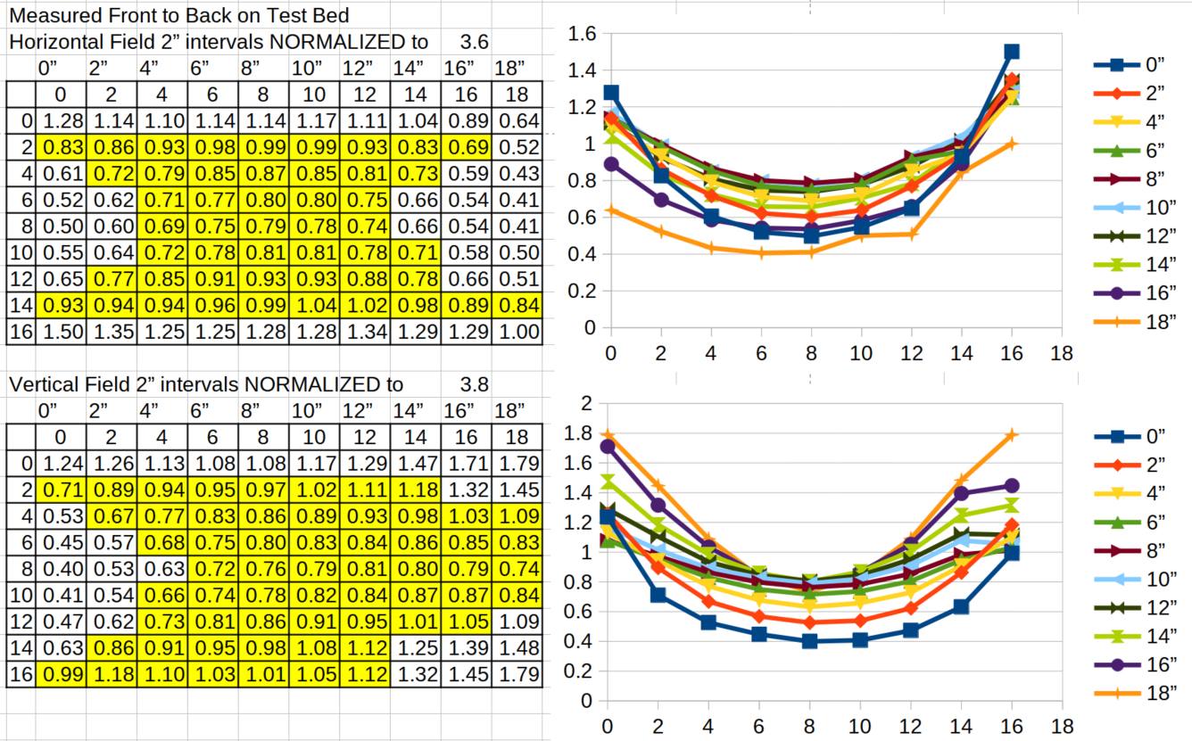
Next is the field uniformity in the front to back direction on the test bed. This direction is worse due to it being the spiral coil narrow direction.
So we need to restrict the treatment width to about 10" to acheive similar uniformity. So that results in an oval shaped reasonably uniform area of about 14" by 10" with a height of about 12".
Total cubic inches is 110"(oval) x 12"height = 1310 sq in.
This compared to a device such as the OncoMagnetic device which uses a small permanent magnet, the target area (for uniformity) likely has to be under one square in.
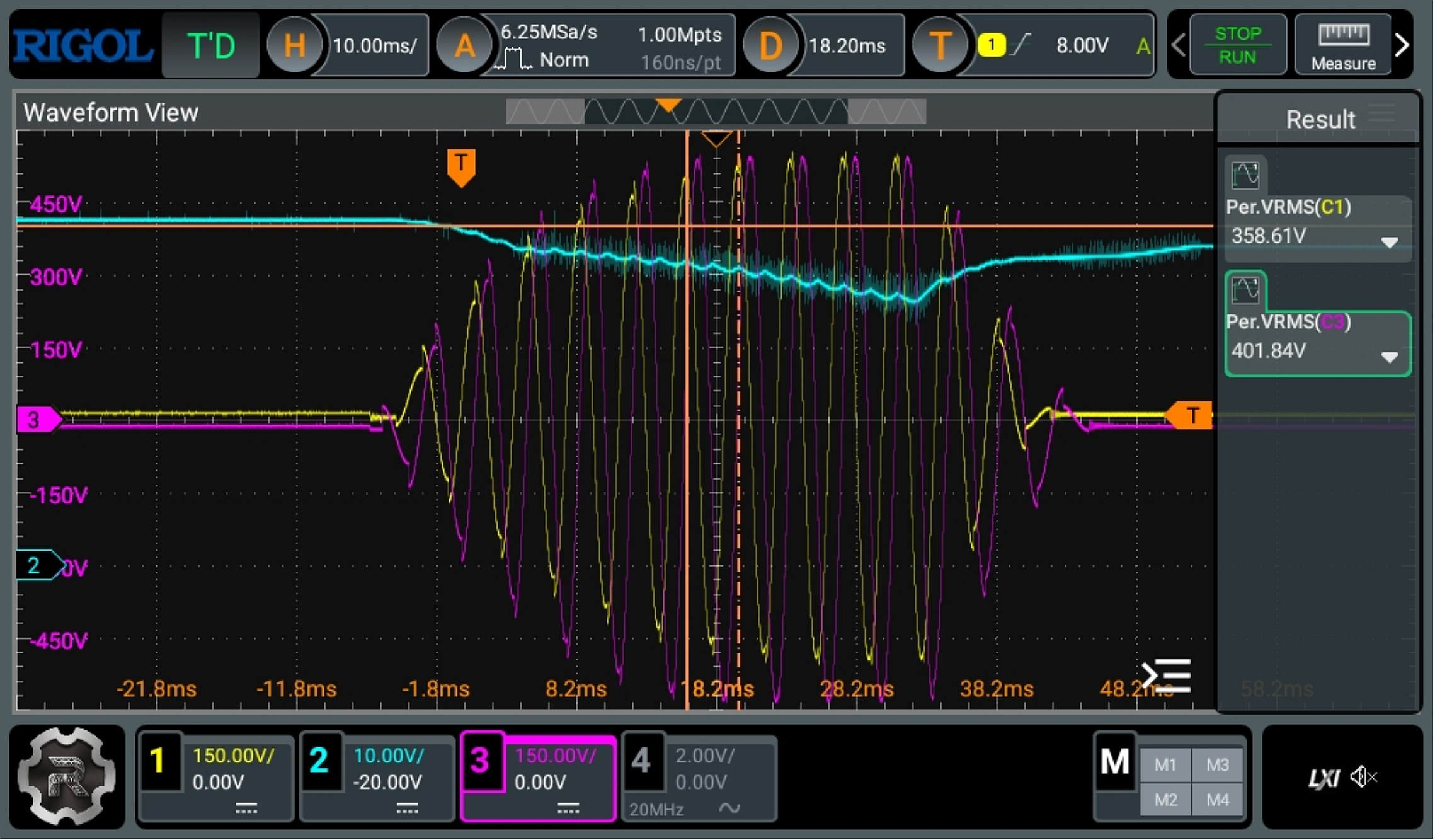
The below scope view is of the highest setting of 9(previous version), which produces a field of 4mTpeak(As of 2024-Sept this is now 5mT peak).
Note the resonant voltage goes to 400V RMS, requiring pulse capacitors rated 600V rms.
Great caution is required at these voltages as it is possible for the voltage to jump through some wire insulation.
(Resulting in possible death)
Also the cyan trace shows the DC/DC converter voltage is not able to keep up, which is why the limit is 4mT peak.
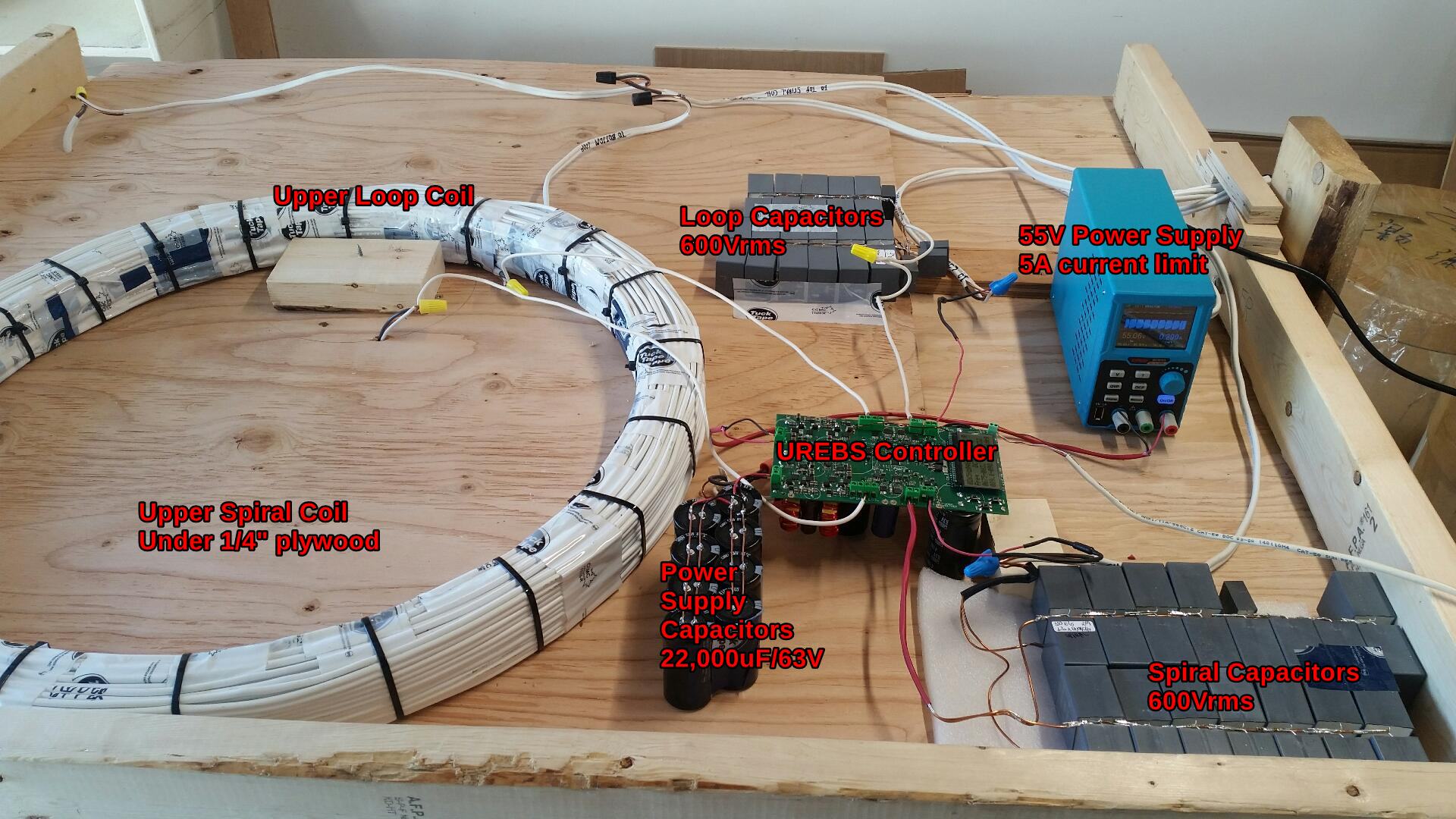
The circuit takes a very high pulse current, so to drive the circuit, it is required to use a 55V (as of 2024 Sept) power supply rated at 5A with proper current limiting.
Proper current limiting means not a hiccup mode type of recovery. This usually means a power supply with an adjustable current limit capability.
Then to handle the pulse current the power supply drives eight 22,000 uF/63V electrolytic capacitors.
When the pulse is generated by the UREBS it takes the necessary pulse current from the capacitors while the power supply goes into current limiting.
Depending on the power setting of the UREBS this could result in up to a 5V voltage drop as the capacitors are discharged.
The capacitors are fully recharged (to 55V) during the off time between bursts.
Changing The Frequency of Operation
The reason for changing the frequency is to change the rate of change of Tesla/sec of the field. Once again caution needs to be expressed,
as it is the rate of change of the field that induces voltages, and possible additional harm to the body. Please review and understand the ICNIRP recommendations, before using any magnetic field.
The frequency of operation of the UREBS can be changed by changing 2 things:
1. The firmware so the frequency of resonance is correct.
2. The Capacitors so the Inductance and Capacitance form the matching resonant frequency.
However lets look at the example of changing from 265 Hz to about 1000Hz. That change is within the practical limits of resonance without changing the inductance of the coils.
Note however that the side effect will be an increase in the resonant voltage. In this case the resonant voltage goes up to about 1400Vrms.
So the capacitors used must be rated to handle this high of voltage. For my test I used the same 600Vrms rated capacitors, but used 3 in series to get a voltage rating of 1800Vrms.
The side effect of using series capacitors is the capacitance drops to 1/3. The increased resonant voltage also is fed back to the control board, so changes in the voltage dividing
is necessary to prevent electrical arcing, and to reduce limits the controll board can handle. In my test case I used 2 external series 470K 3W resistors rated at 750V working voltage each, and placed
these resistors in the feedback line to controller. For safety reasons I placed these resistors close to the connection of resonance, and covered them in heat shrink.
I also changed the divider on the controller to 15K. So I had 470Kx2 and 240Kx4 (all in series) with a 15K resistor to ground.
I placed a X10 scope probe on the 15K resistor and setting the scope to a X1500 probe gave me about the correct readings on the scope.
Reminder that working with high voltage is dangerous, and you also need to take precautions to protect the treatment area from any possiblity of arc'ing, causing electrical shock or death.
Also that these voltages will ark right though electrical insulation. You must provide enough electrical insulation at all points in the circuit.