 Nestronics
Nestronics
Nestronics
This version uses PSPWM (Phase Shift Pulse Width Modulation) to control the field strenght level.
Note that it is recommended you build from the Rev 07 (or higher) documentation.
The difference between 06 and 07 is the addition of the optional relay boards to allow frequency selection.
You can build Rev07 without the relay boards if desired.
Index
UREBS Controller Details
UREBS Schematic
Winding the Coils for the UREBS
Frame Construction for the UREBS
Connection from UREBs to Raspberry Pi
Web Page Control of the UREBS
C++ Firmware plus web page PHP
Gerber Files
Video Illustrating the Magnetic Field effect on Iron Powder
Go directly to Rev 07 Documentation

The MCU generates a clock signal at twice the desired resonant frequency using the internal hardware timers. Each resonant circuit uses a full bridge driver
which requires 2 lines to drive it. We will call these the A and B legs. The A and B legs are both 50% duty cycle signals at the resonant frequency.
When the A and B legs are 180 degs out of phase the full bridge driver, drives the resonance at maximun power capability.
The other extreme is when A and B are in phase, which results in no power delivered from the full bridge driver.
Phase shifts varying from 0 to 180 degs will give a varying amount of power.
Hence the name Phase Shift Modulation. When we have a control signal at twice the frequency of resonance, and we toggle the A leg on every
rising edge, and the B leg on every falling edge we acheive:
1. both A and B legs will always be 50% duty cycle (desireable)
2. Duty Cycle control on the orginal X2 resonant frequency signal controls the phase shift between the A and B legs, and hence controls
the output power delivered from the full bridge driver.
Note that this method allows for power adjustment for each cycle of the output. This is highly desireable as all resonance takes time to build up
to maximun power, and by providing a boost in power to start the resonance reduces the time required to get to the desired output field strenght.
The boost allows a faster rise time during the start of the resonant burst.
Individual Zero crossing detectors, and peak detectors allow feedback to the MCU of the peak resonant voltage and phase of each coil pair.
Since the exact phase at resonant can vary in accuracy, the MCU is capable of adjusting the phase relationship (using a calibration routine)
to ensure the resulting produced phase difference is 90 degs.The software has an calibration routine for
calibrating levels and phase, and saving them.
A Raspberry Pi 5 is used for a Web Server which is accessible over the WiFi built into the Raspberry Pi. Web Page access
(from any phone or tablet, etc) is used to control the setting on the UREBS controller.

Shown below is revision 7 of the PCB which has phase shift control of the A and B legs to allow a high or low drive level.
(Note that Revision 7 uses up to a 55V supply)


Note how 20ga bus wire is used to re-enforce the current handling capability of the PCB. The peak current to start the burst
could be greater than 100A as the multiple 22,000ufd caps discharge.

A Capacitor bank is used for each of the two resonate circuits. The resonate frequency is manually tuned for 265Hz (or desired freq) by increasing/decreasing
capacitance for the peak resonance voltage. The 2nd resonance(the one lagging 90 degrees) is also tuned to ensure and approximate 90 phase shift.
Ideally 90 degrees matches a duty cycle of 50%.
The Capacitors should be rated for pulse use and have a high RMS voltage rating.
Here the capacitors are the Kemet R75 series with a RMS voltage rating of 600V.
Great caution should be used when working with the high voltage produced by this circuit.
Use all caution to prevent electrical shock/death.
Note the Schematic has different pages selected by the tabs. Also the schematic is not yet fully completed but the basics are there.
Link to the SchemeIt schematic and bill of material for the UREBS (note it takes up to 30 seconds to load to see the schematic)
Component details are also under SchemeIT
The are 2 pairs of coils, known as the spiral coils and the loop coils.
The spiral coils are assembled attached to a 48" x48" 1/4" thick sheet of plywood.
The inner diameter is 8.5" and the outer diameter is about 46" (which is about 88 turns).
The Loop coils are 24" inner diameter 6 winding high and 10 deep for a total of 60 turns.
All wire is standard 14ga 3 conductor wire (14/2) commonly used for house wiring.
The 3 conductors are wired in parellal to lower the resistance and reduce the skin effect.
The best way to wind the coils is to build a winding jig.
Shown below is a turn table constructed from a stepper motor and worm gear.
The stepper motor used was a NEMA 24, 24HS34-3008D and it was paired with a 40:1 worm gear reduction.
A DMA860S Stepper motor driver was used (max 8.2A rating) and a small pulser circuit to supply the pulsed
for speed and direction control to the controller. Note that this jig was a bit under powered, and it is recommended
to use a motor with a higher torque capability, perhaps 50% higher.


The Spiral Coil can then be wound as follows: Note that the adhesive is applied each turn.
This is required to hold the winding in place, as one of the coils is installed upside down.

Loop Winding example is as follows. Adhesive is not required as cable ties may be used to hold the winding together.

The core of the winding jig may be removed to allow cable ties to be inserted in the precut slots. This way
the initial cable ties can be installed before removal from the core.

The finished loop coil:

The frame may be constucted out of wood and screws. Ideally it is best to minimize the amount of metal used in the constuction,
as it in theory will have some effect on the generated magnetic field.
The following consideration should be taken into account when building it.
  - strong enough to support the considerable weight of the coils, and anything to be placed in the treatment area.
  - minimize the use of magnetic material
  - able to disassemble for transport, or moving thru doors.
  - easy of access to the treatment area.
In this case a 3' x 3' stand was constructed from 2x6:

Then the lower coil assembly (4'x4') may be built on top of the stand.
The key things to notice are, the requirement to router clearance for the spiral coils in 4 locations in the outer frame,
and how the spiral coil shown in the background is flipped on top to complete the assembly. Notice also the properly
placed recessed wooden supports to support to spiral coil. Note the rotation direction that the coil is installed,
and that the loop coil is raised so the installation will touch the spiral coil windings when installed.
The direction the coils are wound must match the wiring so the coils are correctly wired in series such that the magnetic
fields are additive. The last point is the voltage on the coils can be in excess of 400V RMS, so it is prudent to keep the
ends of the wires seperated. When making any joints in the wire, use properly rated crimp connectors, and add adequate
electrical insulation.

The top assembly is built 16" above the lower assembly mounted such that it can swing on a hinge (bolt).
This allows for easy access to the treatment area. The top assembly is quite heavy, so care should be taken
to ensure the hinge assembly can not fail, such as from bolt failure, or spliting of wood. The example
shown uses a bolt location of 20" up from the lower assembly, and 20" in from the back of the unit. This makes
it possible to almost completely open the unit. The compromise is the hinge point makes the unit unbalanced,
and the front of the unit quite heavy to lift. Hence it is advisable to counter balance the top assembly with
extra weight placed near the back of the top assembly.(shown on a lower picture)

As can be seen from the below picture, the top assembly is the reverse of the lower assembly.
The spiral coil is on the bottom with the loop coil placed directly on top of it. A diagonal support
was used help stop the weight of the coils from sagging the 1/4" plywood. The picture shows a 56 lb concrete
bag used as a counter balance. This will later be mixed into concrete bricks so that if fit in the unit when
the upper 1/4" plywood lid is installed. Another observation is the 2x2 stop blocks on each side at the rear of
the unit. Currently these are held in place with clamps, but will be glued/screwed, when the assembly is complete.

Next comes the placing of the electronics and the wiring. The following pictures show how the 2 loop coils
are connected in series with their resonant capacitors. As well as the 2 spiral coils with their resonant
capacitors.
The initial capacitor values can be selected as follows:
1. measure the Loop series inductance (typ ~8mH)
2. compute the capacitance to resonant at 265Hz
3. Solder together enough capacitors to produce the required uF
4. Repeat for 1-3 for Spiral inductors.
5. When assembled, power up the URBES and tweek the loop capacitor for peak Voltage.
6. Repeat step 5 for spiral resonance.
7. Re-tweek the spiral resonance to have 90 phase shift (mid burst) wrt loop resonance.
The connection of capacitor to coil inductor also has a monitor connnection to the UREBS.
This connection is made thru a 470K high voltage rating resistor to the UREBS.
Notable in the pictures is the connection to the raspberry pi web server. The external monitor/keyboard
is necessary for setup, but is optional for operation, as the configuration is accessible on any device with a web browser.


The power supply is a 55V power supply with a 5A current limit. Note the use of a lab grade power
supply in the above pictures. This is because you want a supply with a 5A constant current limit, not a power supply that
goes into cut off mode (chirp) when the current is exceeded. The 5A current limit will be exceeded during each
burst. It is the job of the multiple 22,000ufd capacitors (6 on pcb, and 8 external) to the supply the large amount
of current to run the 50ms burst. As shown in the oscilloscope capture a burst for the 5mTp level causes a drop of voltage
about 5V. This translates to about 81 joules or 1.5KW of power in each 50ms burst. Or if used on a 2 second repeat schedule
then about 2 joules or 37W average power.

There is a wire connector from the UREBS to the Raspberry Pi, to run the I2C and interrupt lines to the Raspberry Pi.
The wire used is ethernet wire with twisted pair. The white lines (striped) are all connected to ground, and this
helps shield the wires from interference from the magnetic fields. Two ethernet wires are used to have enough wire pairs, and
the lenght can be for example 3ft, depending where you want to mount the raspberry pi.
1st image is the UREBS side connector, and the 2nd image is the Raspberry Pi side. If you are looking for longer term high reliability
I would recommend replacing the 40pin raspberry pi connector with gold plated pins (difficult task), or solder the wires directly
to the raspberry pi connector. Make sure you use gold plated crimp pins, and gold plated pins on the UREBS.
Note in the example picture it uses a 16 pin connector that plugs into the Raspberry Pi 40 pin connector, and that the Orange and Blues
wires line up with pins 3 and 5 on the raspberry pi connector.


The Raspberry Pi has a C++ program that monitors the interrupt lines.
When the raspberry gets an interrupt it performs the I2C communication (as master) with the UREBS.
If it is fetching status information, it stores the status to a text file in a RAM disk (to avoid sdcard wearout).
The web page then displays the status by fetching it from the text file. The reverse is also true.
Requests for mode changes are saved to a text file by the web page, that is then transferred by the C++ program to the UREBS.
Once configured the UREBS is accessible for control using any web browser. Shown below is a prototype web page interface.
Notice the magnetic field level is adjustable from 0.5mTpeak to 5mTpeak, and the field mode selection can be Horizontal, Vertical,
Clockwise rotation, Counter Clockwise rotation, or various alternating patterns. The treatment schedule can be set to any on/off time,
and if the schedule is a repeating schedule.
Then there is the calibration capability. To have a proper rotating field both the horizonal and vertical field should be of
equal field strenght and have a 90 degree phase shift. The UREBS can do a calibration routine (may take up to 1 hour) to calibrate
all the levels, and modes. The calibration will remain valid as long as the power supply conditions do not change.
Before doing any calibration the Default Calibration files should be sent to the UREBS unit.
The UREBS Status section displays the current status (requires a brower refresh to update).
The Horz/Vert levels are raw ADC readings for the peak level of each burst cycle.
The Phase listing is the approximate phase error (wrt 90 deg) for each cycle of the burst.

The main MicroController is a Texas Instruments MSP430FR5739IRHAT that has 16KB of FRAM.
It can be programmed using the CCS (Code Composer Studio) that is free from TI.
You can program it with an Experimenters board
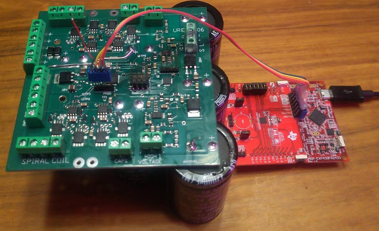
or a Flash Emulation Tool.
In both cases you need to build a custom 2 wire (4 wires with power and ground) programming cable.
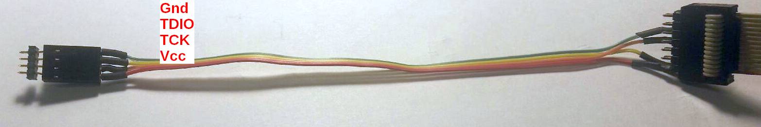
main MCU1 firmware download link
There is also a 2nd MCU, the MSP430FR2433, used to monitor levels. It can be programmed with the same programmer and cable.
firmware download link
The Raspberry Pi must have the apache/php web server software install, as well as cpp.
The c plus plus program interfaces with the I2C interface to the UREBS. Then the web server, serves that information so
that the UREBS can be controlled from a simple web page.
download cpp firmware
download web page
UREBS revision 7 gerber files download link
This version of PCB (printed circuit board) has removed some artwork errors, but has not been tested yet.
Note please review the readme file for instruction on order parameters.
You would also want to order a solder screen, to allow assembly of the board.
All our PCB's are build by hand, using air tool placement, and reflowed in a low cost portable reflow oven.
Thru hole components are then installed.
A part placement guide can be downloaded here .
We commonly print out a few copies and use different colors of highlighters to mark same value of components.
This greatly speeds the placement rate.